|
|
|
|
|
|
|
|
ROBERTSON
VENTILATION INTERNATIONAL
| ||||||||
|
ROBERTSON
VENTILATION INTERNATIONAL | ||||||||
|
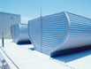
Exhaust Systems |
| ||||||||||||||||||||||||||||||||||||||||||||||||||||||||||||||||||||||||||||||||||||||||||||||||||||||||||||||||||||||||||||||||||||||||||||||||||||||||||||||||||||||||||||||||||||||||||||||
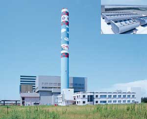
The Ultra-Flow Continuous Gravity Ventilator is the most aerodynamically efficient in the RVI range of exhaust ventilators. The Ultra-Flow provides an energy and cost effective means of air exhaust for severe heat and fume problems. Ideally suited to application in aluminium smelters, steel mills, boiler houses, glass plants and general industrial manufacturing facilities. |
| ||||||||||||||||||||||||||||||||||||||||||||||||||||||||||||||||||||||||||||||||||||||||||||||||||||||||||||||||||||||||||||||||||||||||||||||||||||||||||||||||||||||||||||||||||||||||||||||
|
Design features
| ||||||||||||||||||||||||||||||||||||||||||||||||||||||||||||||||||||||||||||||||||||||||||||||||||||||||||||||||||||||||||||||||||||||||||||||||||||||||||||||||||||||||||||||||||||||||||||||
| |||||||||||||||||||||||||||||||||||||||||||||||||||||||||||||||||||||||||||||||||||||||||||||||||||||||||||||||||||||||||||||||||||||||||||||||||||||||||||||||||||||||||||||||||||||||||||||||
| |||||||||||||||||||||||||||||||||||||||||||||||||||||||||||||||||||||||||||||||||||||||||||||||||||||||||||||||||||||||||||||||||||||||||||||||||||||||||||||||||||||||||||||||||||||||||||||||
|
The ventilators shall be of the Ultra-Flow Continuous Gravity type as manufactured by HH Robertson and shall be the sizes shown on drawings. The ventilators shall have a proven Coefficient of Discharge of 0.65, as certified by an independent test authority and shall have an exhaust capacity of ?m3/sec/m/run, based upon ?..°C temperature difference and ?.m effective height, for thermal effect only (ie, zero wind velocity) and shall be sized accordingly. The ventilators shall be designed to perform as specified regardless of wind velocity or direction. The ventilators shall be designed to withstand the wind loads generated by a wind speed of ?.m/s in a Terrain Category ?? when centred ?..metres above ground level. (Alternative wind conditions to be provided to suit local code requirements.) The ventilators shall be watertight under all normal positive pressure conditions. The ventilators shall be capable of self-cleaning action by the elements with provisions for carrying water and normal wind transported soil material to outside the ventilator. The ventilators shall have a free exhaust area at their top of two times the throat opening. The total air path through the ventilators is to be equal or larger than the throat opening. The ventilators shall be equipped with wind jump diaphragms spaced at each structural frame to afford efficient ventilation regardless of wind direction. The ventilators shall have a cap peak flash and shall have gutters complete with downspouts spaced at not over 6m centres, to drain precipitation from the cap without clogging. The ventilators shall be equipped with guiding vanes to aid the passage of exhaust air through the ventilator and to aid the distribution of the exhaust air across the outlet opening at the top. The dampers (where fitted) shall be an integral part of the ventilator and shall form an inverted cone under the cap, protecting the operating mechanism by keeping it out of the exhaust air stream when the dampers are in the open position. (Method of operation of the dampers to be specified separately and to be of type to suit individual client eg manual, electrical, pneumatic.) The ventilators shall be constructed of (select one): Versacor Protected Metal, Zincalume - Plain or Painted, Aluminium. Sheeting profiled to withstand the design wind load above, all flashings shall be of the same material as the sheeting. Ventilator structural framework shall be hot dip galvanised (alternative or additional coating systems to be specified also eg, high build epoxy).
| |||||||||||||||||||||||||||||||||||||||||||||||||||||||||||||||||||||||||||||||||||||||||||||||||||||||||||||||||||||||||||||||||||||||||||||||||||||||||||||||||||||||||||||||||||||||||||||||
| Contact your nearest RVI service centre for performance details and technical advice. | |||||||||||||||||||||||||||||||||||||||||||||||||||||||||||||||||||||||||||||||||||||||||||||||||||||||||||||||||||||||||||||||||||||||||||||||||||||||||||||||||||||||||||||||||||||||||||||||